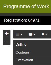
Using the Spatial Section
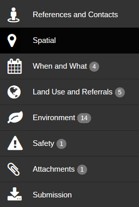
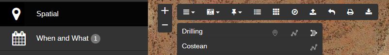
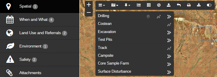
Enter the Spatial section by clicking on the left hand side bar on the screen:
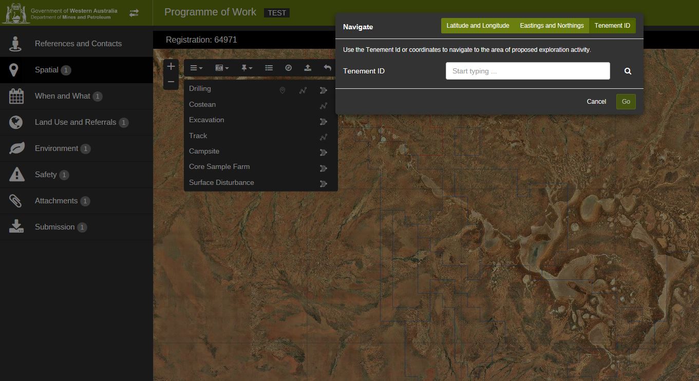
The Navigate box pops up automatically when you enter the Spatial section for the first time on a new application.
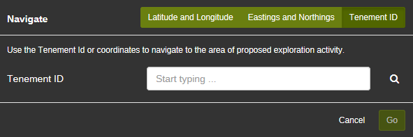
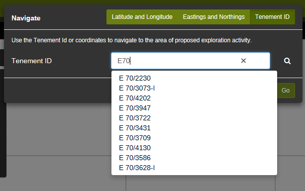
Select the tenement from the drop down list that appears then select "Go".
The map will pan to the area of the tenement or coordinates you selected.
Hint: When the map has panned to the tenement location, it helps to switch off aerial imagery and zoom in to see the tenement labels and boundaries clearly.
Zoom in and out using the + and - icons on screen:
If the Navigate box disappears while moving between sections or when editing an existing application you can make it reappear by selecting the Navigate icon from the Tool Bar located in the top left hand area of the Spatial section:
Navigate Icon: ![]()
Tool Bar: ![]()
Tool Bar Icons
Use the Tool Bar found in the top left area of the Spatial section to select functions:
The following functions are available on the Tool Bar (hint: Hover over an icon for the label to appear):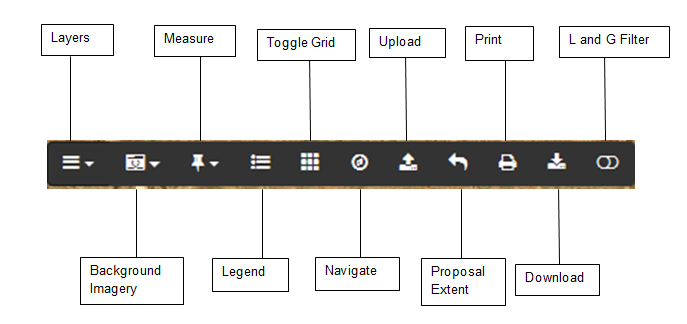
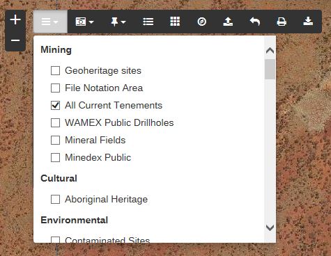
Layers: Use the Layers function to switch on and off spatial layers:
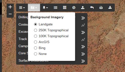
Background Imagery: use this function to select the background imagery type or to turn imagery off.
![]() Measure: use this icon to measure the distance or area of a rectangle/polygon.
Measure: use this icon to measure the distance or area of a rectangle/polygon.
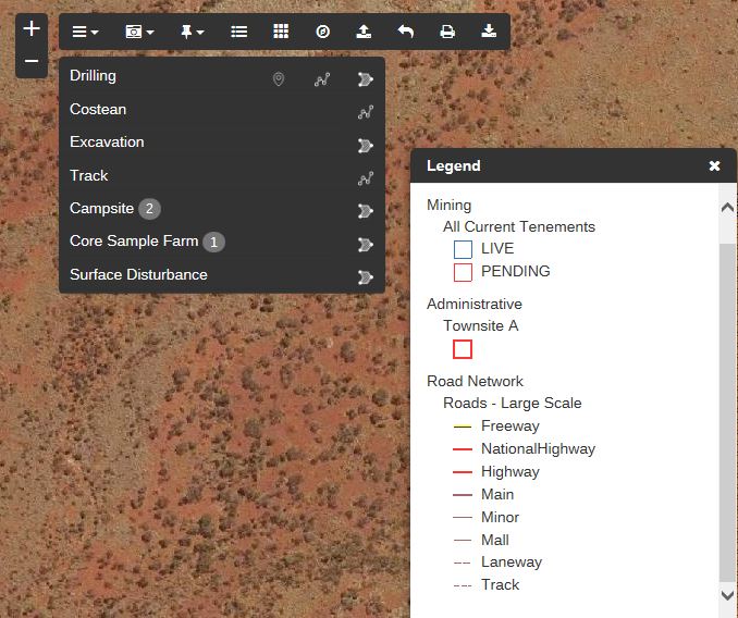
![]() Legend: click the legend icon to display the legend for all active layers.
Legend: click the legend icon to display the legend for all active layers.
![]() Toggle Grid: use to turn on and off the grid
Toggle Grid: use to turn on and off the grid
![]() Navigate: enter tenement ID or coordinates.
Navigate: enter tenement ID or coordinates.
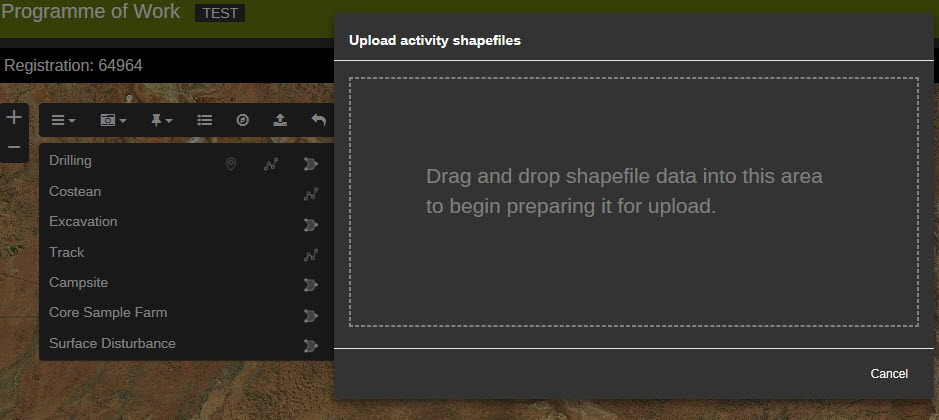
![]() Upload: use this function to upload shapefiles.
Upload: use this function to upload shapefiles.
![]() Proposal Extent: click the proposal extent function to zoom to the extent of saved drawings/activities entered.
Proposal Extent: click the proposal extent function to zoom to the extent of saved drawings/activities entered.
![]() Print: click to generate a PDF map of the current lodgement.
Print: click to generate a PDF map of the current lodgement.
![]() Download: click to download shapefiles for the entered drawings.
Download: click to download shapefiles for the entered drawings.
![]() Click to filter out L and G Tenements: Option to toggle on and off L and G tenement types. The button is toggled to off, so L and G tenements are ignored. This can be turned on and off when needed.
Click to filter out L and G Tenements: Option to toggle on and off L and G tenement types. The button is toggled to off, so L and G tenements are ignored. This can be turned on and off when needed.
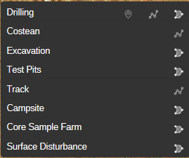
There are eight categories of activity types available on the menu, located under the Tool Bar, as shown below:
Adding a new Activity
Click on an icon from the right side of the activity menu to select a drawing tool. You will see the options associated with that activity change to include a cancel action.
To start the drawing single click on the map. If it's a polygon, use a single click for each corner. Double click to finish the drawing. An attribute table will pop up prompting further details about the proposed activity. For information on how to complete the attribute table for each activity type, please visit the relevant section under "Activity Types".
Your new activity will be saved once you click the Save option associated with the attribute table. The save action shows as a spinner. Please wait until the spinner has completed before drawing your next activity or navigating to a new page.
The PoW will calculate the size and, if appropriate, tonnage disturbed while you are completing the attribute table. These details can be seen in the "Show advanced options" area.
Editing or deleting an existing activity
To edit or delete an existing activity, click on the activity in the map. You may need to zoom in to successfully select the activity. If you don't click directly on the activity, the details of the tenement will be displayed instead.
Once the activity is selected, the associated activity menu will change:
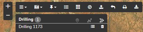
Click on the table icon to bring back the attribute table. Click on the trash can to delete the drawing.
Restrictions when Drawing
You cannot draw an activity outside the bounds of a live tenement.
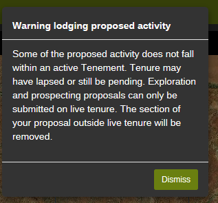
If you believe you have received this message in error, please contact the EARS Online / EARS 2 enquiries line: +61 8 9222 3535.
Drilling Activities
Once you have navigated to the proposed area of activity, select the appropriate icon from the menu to draw the proposed drilling activities (hint: hover over the icon for its label). Drilling activities can be entered as individual drill holes, drill lines with standard spacing, or a drilling area, if precise lines are unknown:
![]()
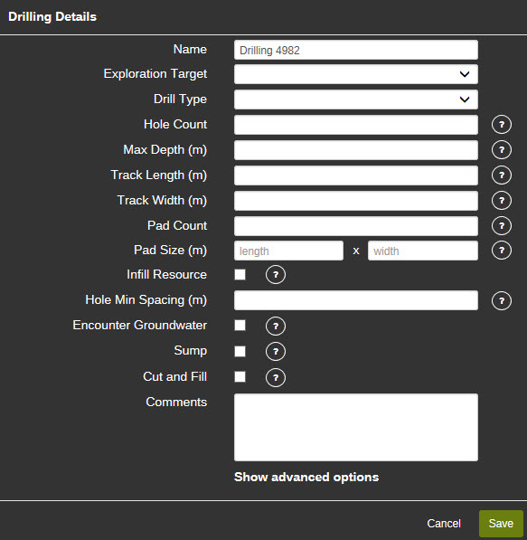
Draw a drill hole by using a single click on the proposed location. An attribute table will pop up requiring you to enter further information about the activity before it can be saved.
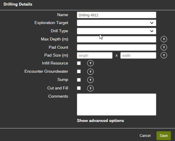
The following information needs to be entered before the drawing can be saved:
- Name: Enter a name for the drill hole (a default name will be provided if nothing is entered).
- Exploration Target: select mineral or water.
- Drill Type: select from auger, air core, rotary air blast, vacuum, sonic, reverse circulation, diamond core, rotary mud or other. If other is selected, you will be prompted to enter the type of drilling.
Hint: if different types of drilling are proposed in the same location then separate drawings should be made for each type. Refer to 'How Do I' for an example of entering multiple drilling types.
- Max Depth (m): enter the maximum depth of the proposed drill hole
- Pad Size: enter length x width pad dimensions in metres. If no pads are required please enter "0" as this is a mandatory field.
- Infill Resource: tick if the drilling program is in the infill/resource drilling phase.
- Encounter Groundwater: select if groundwater is expected to be encountered; if so, sumps or alternative water containment methods will need to be specified.
- Sumps: select if a sump is required, enter dimensions and specify whether the sump will be located within the pad or will be additional to disturbance required for the pad.
- Cut Fill: select if cut and fill techniques will be used for this drill hole. Enter slope degrees and bulk density of the material (defaults to 1.5).
- Comments: enter any additional comments. If you are using an alternative water containment method to a sump, enter details in this section.
Once all the required information has been entered, hit save and the drawing (including buffer) will appear on the map. You must click Save to save the details and the drawing. If invalid information is supplied, the field will be cleared. If the field is mandatory, the label will change to red.
There is a limit of 500 drill points in one upload. Please consider using drill lines and drill areas that allow more drill holes.
Advanced options:
Click on the show advanced options to display the additional information. Select hide advanced options to hide the additional information. Under advanced options for the drill hole, you will find:
1. Calculated Information
2. Approval Buffer
Calculated Information
The calculated information will display:
- Proposed Area Disturbed (hectares)
- Proposed Mass Disturbed (tonnes)
- MRF Rehabilitated Liability Estimate* (RLE)
- MRF Estimated Levy*
*Indicative MRF RLE and Estimated Levy provided for your information.
Approval Buffer
The default buffer for a drill hole is set at 20 metres. You can request to increase this buffer, however please note that increasing the buffer may attract additional requests for information from the assessing officer.
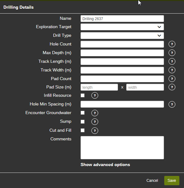
To draw a drill line, use a single click then a double click to finish the drawing. An attribute table will pop up requiring you to enter further information about the activity.
The following information needs to be entered before the drawing can be saved:
- Name: Enter a name for the drill hole (a default name will be provided if nothing is entered).
- Exploration Target: select mineral or water.
- Drill Type: select from auger, air core, rotary air blast, vacuum, sonic, reverse circulation, diamond core, rotary mud or other. If other is selected, you will be prompted to enter the type of drilling.
Hint: if different types of drilling are proposed in the same location then separate drawings should be made for each type of drilling. Refer to 'How Do I' for an example of entering multiple drilling types.
- Hole Count: enter the maximum number of drill holes anticipated on the drill line.
- Max Depth (m): enter the maximum depth of the proposed drill line (maximum depth of any individual drill hole rather than cumulative depth)
- Track length (m): enter the proposed track length to be cleared as part of the drill line in metres (see 'Advanced Options' for the calculated length of the drawing). If no track clearing is required, please enter "0" as this is a mandatory field.
- Track width (m): enter the proposed track width in metres
- Pad Size: enter length x width drill pad dimensions in metres. If no drill pads are required please enter "0" as this is a mandatory field.
- Infill Resource: tick if the drilling program is in the infill/resource drilling phase.
- Hole spacing: enter the minimum planned distance between any two drill holes in metres.
- Encounter Groundwater: select if groundwater is expected to be encountered; if so, sumps or alternative water containment methods will need to be specified in the following questions.
- Sumps: select if a sump is required, enter dimensions and specify whether the sump will be located within the pad or will be additional to disturbance required for the pad.
- Cut Fill: select if cut and fill techniques will be used for this drill line. Enter slope degrees and bulk density of the material (defaults to 1.5).
- Comments: enter any additional comments if you are using an alternative water containment method to a sump, enter details in this section
Once all the required information has been entered, hit save and the drawing (including buffer) will appear on the map. You must click Save to save the details and the drawing. If invalid information is supplied, the field will be cleared. If the field is mandatory, the label will change to red.
Advanced options:
Click on the show advanced options to display the additional information. Select hide advanced options to hide the additional information. Under advanced options for the drill line, you will find:
1. Calculated Information
2. Approval Buffer
Calculated Information
The calculated information will display:
- Proposed Area Disturbed (hectares)
- Proposed Mass Disturbed (tonnes)
- Length
- MRF Rehabilitated Liability Estimate* (RLE)
- MRF Estimated Levy*
*Indicative MRF RLE and Estimated Levy provided for your information.
Approval Buffer
The default buffer for a drill line is set at 20 metres. You can request to increase this buffer, however please note that increasing the buffer may attract additional requests for information from the assessing officer.
To draw a drill area, use a single click for each corner of the polygon followed by a double click to complete the drawing. An attribute table will pop up requiring you to enter further information about the activity.
The following information needs to be entered before the drawing can be saved:
- Name: Enter a name for the drill hole (a default name will be provided if nothing is entered).
- Exploration Target: select mineral or water.
- Drill Type: select from auger, air core, rotary air blast, vacuum, sonic, reverse circulation, diamond core, rotary mud or other. If other is selected, you will be prompted to enter the type of drilling.
Hint: if different types of drilling are proposed in the same location then separate drawings should be made for each type of drilling. Refer to 'How Do I' for an example of entering multiple drilling types.
- Hole Count: enter the maximum number of drill holes anticipated within the drilling area.
- Max Depth (m): enter the maximum depth of the proposed drill area (maximum depth of any individual drill hole rather than cumulative depth)
- Track length (m): enter the proposed track length to be cleared as part of the drill area in metres. If no track clearing is required, please enter "0" as this is a mandatory field.
- Track width (m): enter the proposed track width in metres
- Pad Size: enter length x width drill pad dimensions in metres. If no drill pads are required please enter "0" as this is a mandatory field.
- Infill Resource: tick if the drilling program is in the infill/resource drilling phase.
- Hole spacing: enter the minimum planned distance between any two drill holes in metres.
- Encounter Groundwater: select if groundwater is expected to be encountered; if so, sumps or alternative water containment methods will need to be specified in the following questions.
- Sumps: select if a sump is required, enter dimensions and specify whether the sump/s will be located within the pad or will be additional to disturbance required for the pad.
- Cut Fill: select if cut and fill techniques will be used in this drilling area. Enter slope degrees and bulk density of the material (defaults to 1.5).
- Comments: enter any additional comments. If you are using an alternative water containment method to a sump, enter details in this section.
Once all the required information has been entered, hit save and the drawing (including buffer) will appear on the map. You must click Save to save the details and the drawing. If invalid information is supplied, the field will be cleared. If the field is mandatory, the label will change to red.
Advanced Options
Click on show advanced options to display the additional information. Select hide advanced options to hide the additional information. Under advanced options for the drill area, you will find:
- Calculated Information
- Approval Buffer
Calculated Information
The calculated information will display:
- Proposed Area Disturbed (hectares)
- Proposed Mass Disturbed (tonnes)
- MRF Rehabilitated Liability Estimate* (RLE)
- MRF Estimated Levy*
*Indicative MRF RLE and Estimated Levy provided for your information.
Approval Buffer
The drilling area boundary acts as the approval buffer therefore no additional buffer applies.
Costean
Use a single click to start drawing the costean then double click to finish the drawing. A table will pop up requiring you to enter further information about the activity.
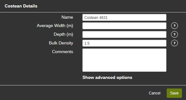
The following information needs to be entered before the drawing can be saved:
- Name: A default name will be provided if nothing is entered,
- Length (m): Enter the average length of the costean in metres,
- Width (m): Enter the average width of the costean in metres,
- Depth (m): Enter the maximum depth of the costean in metres,
- Bulk Density: Enter the bulk density of the material.
Once all the required information has been entered, hit save and the drawing (including buffer) will appear on the map. You must click Save to save the details and the drawing. If invalid information is supplied, the field will be cleared. If the field is mandatory, the label will change to red.
Advanced options
Click on show advanced options to display the additional information. Select hide advanced options to hide the additional information. Under advanced options for the costean, you will find:
1. Calculated Information
2. Approval Buffer
Calculated Information
The calculated information will display:
- Proposed Area Disturbed (hectares)
- Proposed Mass Disturbed (tonnes)
- Length of the drawing
- MRF Rehabilitated Liability Estimate* (RLE)
- MRF Estimated Levy*
*Indicative MRF RLE and Estimated Levy provided for your information.
Approval Buffer
The default buffer for a costean is set at 20 metres. You can request to increase this buffer, however please note that increasing the buffer may attract additional requests for information from the assessing officer.
Excavation
Use single clicks to draw the excavation then double click to finish the drawing. A table will pop up requiring you to enter further information about the activity:
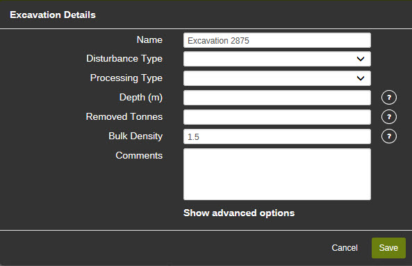
The following information needs to be entered before the drawing can be saved:
- Name: Enter a name for the excavation (a default name will be provided if nothing is entered).
- Disturbance Type: Select from the drop down menu – borrow pit, bulk sampling, hostile material deposit type, other, scrape and detect, small shafts, soil test pits, test pits.
- Processing Type: Select from alluvial wet plant, dry blowing, none, other or small plant. Note: enter ‘none’ if processing is not required as this is a mandatory field.
- Depth (m): Enter the depth of the disturbance (metres) at the deepest point.
- Removed tonnes: Refers to the number of tonnes that will be transported off tenure (rather than tonnes removed from the ground). Only enter a number here if you intend to transport tonnage off tenure.
- Bulk Density: Please enter the bulk density of the material.
Once all the required information has been entered, hit save and the drawing (including buffer) will appear on the map. You must click Save to save the details and the drawing. If invalid information is supplied, the field will be cleared. If the field is mandatory, the label will change to red.
Advanced options
Click on show advanced options to display the additional information. Select hide advanced options to hide the additional information. Under advanced options for excavations you will find:
1. Calculated Information
2. Approval Buffer
Calculated Information
The calculated information will display:
- Proposed Area Disturbed (hectares)
- Proposed Mass Disturbed (tonnes)
- MRF Rehabilitated Liability Estimate (RLE)
- MRF Estimated Levy
Approval Buffer
The default buffer for an excavation is set at 50 metres. You can request to increase this buffer, however please note that increasing the buffer may attract additional requests for information from the assessing officer.
Note: tonnage calculated based on the drawing and dimensions will appear in the advanced options section for your information once you have entered the dimensions.
Track
Use single clicks to draw the access track then double click to finish the drawing. A table will pop up requiring you to enter further information about the activity.
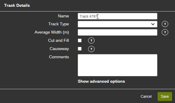
The following information needs to be entered before the drawing can be saved:
- Name: Enter a name for the excavation (a default name will be provided if nothing is entered).
- Track Type: Select from the three options for track type:
- Existing "authorised under prior PoW" (enter the Reg ID that the track was approved under), or
- Existing "other" (source of the track e.g. pastoral track, mining proposal; or
- New.
Note: if the proposal involves widening an existing track, select "new" and specify the width of the widened portion.
- Width (m): Enter the average width in metres.
- Cut and Fill: If cut and fill methods will be used please tick the relevant box and enter the slope degrees and bulk density.
- Causeway: If the track is will be built above the normal height of the ground (i.e. a causeway), please tick the box and enter the proposed height in metres.
- Comments: enter any additional comments.
Once all the required information has been entered, hit save and the drawing (including buffer) will appear on the map. You must click Save to save the details and drawing. If invalid information is supplied, the field will be cleared. If the field is mandatory, the label will change to red.
Advanced options
Click on show advanced options to display the additional information. Select hide advanced options to hide the additional information. Under advanced options for the track you will find:
1. Calculated Information
2. Approval Buffer
Calculated Information
The calculated information will display:
- Proposed Area Disturbed (hectares)
- Proposed Mass Disturbed (tonnes)
- Length (of the drawing in kilometres)
- MRF Rehabilitated Liability Estimate* (RLE)
- MRF Estimated Levy*
*Indicative MRF RLE and Estimated Levy are provided for your information.
Approval Buffer
The default buffer for a track is set at 20 metres. You can request to increase this buffer, however please note that increasing the buffer may attract additional requests for information from the assessing officer.
Please note the buffer only applies to new tracks and does not apply to existing tracks.
Campsite
Use single clicks to draw the campsite then double click to finish the drawing. A table will pop up requiring you to enter further information about the proposed activity.
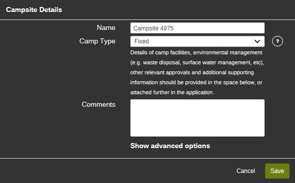
The following information needs to be entered before the drawing can be saved:
- Name: Enter a name for the campsite (a default name will be provided if nothing is entered).
- Camp Type: Select from Fixed or Mobile (fixed refers to semi-permanent infrastructure such as dongas or containers; mobile refers to a fly camp made up of tents, mobile trailers, etc).
- Comments: Details of camp facilities, environment management, other relevant approvals and additional supporting information should be provided in the space below, or attached in the application (i.e. under Attachments).
Once all the required information has been entered, hit save and the drawing (including buffer) will appear on the map. You must click Save to save the details and the drawing. If invalid information is supplied, the field will be cleared. If the field is mandatory, the label will change to red.
Advanced options
Click on show advanced options to display the additional information. Select hide advanced options to hide the additional information. Under advanced options for camps, you will find:
1. Calculated Information
2. Approval Buffer
Calculated Information
The calculated information will display:
- Proposed Area Disturbed (hectares)
- MRF Rehabilitated Liability Estimate* (RLE)
- MRF Estimated Levy*
*Indicative MRF RLE and Estimated Levy are provided for your information.
Approval Buffer
The default buffer for a camp is set at 20 metres. You can request to increase this buffer, however please note that increasing the buffer may attract additional requests for information from the assessing officer.
Core Sample Farm
Use single clicks to draw the proposed core sample farm then double click to finish the drawing. A table will pop up requiring you to enter further information about the activity.
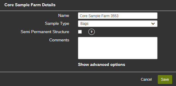
- Name: Enter a name for the core sample farm (a default name will be provided if nothing is entered).
- Sample Type: Select from the drop down menu: bags, core or both.
- Semi Permanent Structure: Tick if a semi permanent structure will be erected (e.g. a donga container).
- Comments: Enter additional comments.
Once all the required information has been entered, hit save and the drawing (including buffer) will appear on the map. You must click Save to save the details and the drawing. If invalid information is supplied, the field will be cleared. If the field is mandatory, the label will change to red.
Advanced options
Click on show advanced options to display the additional information. Select hide advanced options to hide the additional information. Under advanced options for core sample farm, you will find:
1. Calculated Information
2. Approval Buffer
Calculated Information
The calculated information will display:
- Proposed Area Disturbed (hectares)
- MRF Rehabilitated Liability Estimate* (RLE)
- MRF Estimated Levy*
*Indicative MRF RLE and Estimated Levy are provided for your information.
Approval Buffer
The default buffer for a core sample farm is set at 20 metres. You can request to increase this buffer, however please note that increasing the buffer may attract additional requests for information from the assessing officer.
Surface Disturbace
Use single clicks to draw the proposed surface disturbance then double click to finish the drawing. A table will pop up requiring you to enter further information about the activity.
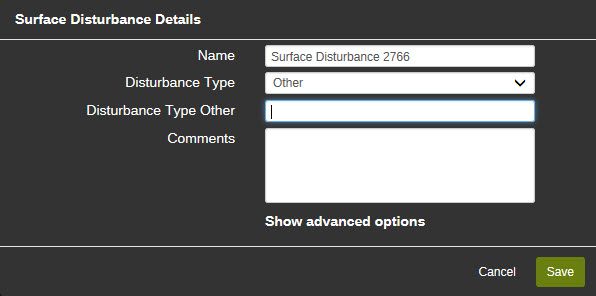
The following information needs to be entered before the drawing can be saved:
- Name: Enter a name for the laydown area (a default name will be provided if nothing is entered).
- Disturbance Type: Select from the dropdown menu - Laydown Area or Other (if you select 'Other', you will be prompted to enter a description of the disturbance).
- Comments: Enter additional comments
Once all the required information has been entered, hit save and the drawing (including buffer) will appear on the map. You must click Save to save the details and the drawing. If invalid information is supplied, the field will be cleared. If the field is mandatory, the label will change to red.
Advanced options
Click on show advanced options to display the additional information. Select hide advanced options to hide the additional information. Under advanced options for camps, you will find:
1. Calculated Information
2. Approval Buffer
Calculated Information
The calculated information will display:
- Proposed Area Disturbed (hectares)
- MRF Rehabilitated Liability Estimate* (RLE)
- MRF Estimated Levy*
*Indicative MRF RLE and Estimated Levy are provided for your information.
Approval Buffer
The default buffer for a surface disturbance is set at 20 metres. You can request to increase this buffer, however please note that increasing the buffer may attract additional requests for information from the assessing officer.
Test Pits
Use single clicks to draw the test pit then double click to finish the drawing. A table will pop up requiring you to enter further information about the activity:
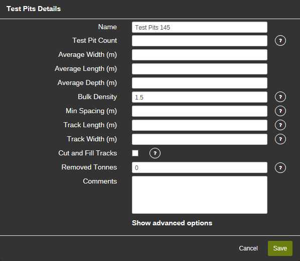
The following information needs to be entered before the drawing can be saved:
- Name: Enter a name for the test pit (a default name will be provided if nothing is entered).
- Test Pit Count: Enter the maximum number of test pits anticipated within the test pit area.
- Width: Enter the average width of the test pits (metres).
- Length: Enter the average length of the test pits (metres).
- Depth (m): Enter the average depth of the test pits (metres).
- Bulk Density: Please enter the bulk density of the material.
- Minimum Spacing: Enter the minimum planned distance between any two test pits in metres.
- Track Length: Enter the proposed track length to be cleared as part of the test pit area in metres. If no track clearing is required, please enter "0" as this is a mandatory field.
- Track Width: Enter the proposed track width in metres.
- Cut and Fill Tracks: Select if cut and fill techniques will be used in the test pit area. Enter slope degrees and bulk density of the material (defaults to 1.5).
- Removed tonnes: Refers to the number of tonnes that will be transported off tenure (rather than tonnes removed from the ground). Only enter a number here if you intend to transport tonnage off tenure.
Once all the required information has been entered, hit save and the drawing will appear on the map. You must click Save to save the details and the drawing. If invalid information is supplied, the field will be cleared. If the field is mandatory, the label will change to red.
Advanced options
Click on show advanced options to display the additional information. Select hide advanced options to hide the additional information. Under advanced options for excavations you will find:
1. Calculated Information
2. Approval Buffer
Calculated Information
The calculated information will display:
- Proposed Area Disturbed (hectares)
- Proposed Mass Disturbed (tonnes)
- MRF Rehabilitated Liability Estimate (RLE)
- MRF Estimated Levy
Approval Buffer
The default buffer for a test pit is set at 0 metres. You can request to increase this buffer, however please note that increasing the buffer may attract additional requests for information from the assessing officer.
Note: tonnage calculated based on the drawing and dimensions will appear in the advanced options section for your information once you have entered the dimensions.